
Friday, December 30, 2011
Lower A-Arm: The Realization
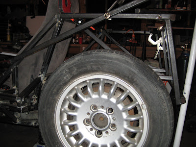
While pulling everything apart, I put the front end back together to take a moment and appreciate all the work I'd accomplished the days before. I even attached the steering linkage and turned the wheel around a couple of... oh crap! I only get one full turn out of the wheel before the rim makes contact with the lower a-arm.
 Since I'm not a huge fan of 17 point turns to flip a U, it looks like it's back to the drawing board for round three of lower a-arm design and rebuild.
Thursday, December 29, 2011
D69: Upper A-Arm D1 + Engine Removal
With the lower arms together, it was time to get the upper arms built. These are much easier to assemble as they are adjustable and don't require everything to be precisely positioned.
The concept here is very similar to that of Jim McSorely over at sevenesque.com except a little more homemade. I got the weld bungs for a great discount making it cheaper to make my own tubes instead of getting real swaged tubes.
My wife and I were having people over for New Years Eve and the garage was needed for some of the festivities... so I began pulling everything apart. Learning from my last experience of installing the motor, I decided to remove the tube that goes across the top of the transmission right behind the engine block. This allowed me to lift the engine straight up and out. Much easier. I plan on making that tube removable to make this process easier in the future without having to cut that tube out every time.

The concept here is very similar to that of Jim McSorely over at sevenesque.com except a little more homemade. I got the weld bungs for a great discount making it cheaper to make my own tubes instead of getting real swaged tubes.
Front tube with fixed end.
 |
Rear tube with clevis end.
 |
Upper assembly attached to the spindle.
The tabs on the ball joint sleeve are cut from 3/8" plate.
The tabs on the ball joint sleeve are cut from 3/8" plate.
 |
 |
My wife and I were having people over for New Years Eve and the garage was needed for some of the festivities... so I began pulling everything apart. Learning from my last experience of installing the motor, I decided to remove the tube that goes across the top of the transmission right behind the engine block. This allowed me to lift the engine straight up and out. Much easier. I plan on making that tube removable to make this process easier in the future without having to cut that tube out every time.

Wednesday, December 28, 2011
D68: Lower A-Arm D2
The second day working on the lower a-arm started out with a new design. Attach the tubes directly to the ball joint sleeve. This required some grinding to get all the necessary notches into the tubes. I needed something to easily hold a tube while I could grind it down.


 I am much happier with the second iteration of the a-arm design.
A quick note here. Use a threaded rode when mocking up the bushing sleeves before tacking them in place. This will ensure they are straight and won't bind with travel. I thought I had a decent jig setup until I installed the arm on the frame with the rear mount loose and realized the mount moved when rotating the arm. Turns out the bushing sleeves weren't in line.
The tube holder device thingy.

The front tube and ball joint sleeve mocked up.

The finished product installed.

Both sides finished. One with a ball joint installed.

Lower a-arm with spindle installed.

A quick note here. Use a threaded rode when mocking up the bushing sleeves before tacking them in place. This will ensure they are straight and won't bind with travel. I thought I had a decent jig setup until I installed the arm on the frame with the rear mount loose and realized the mount moved when rotating the arm. Turns out the bushing sleeves weren't in line.
Tuesday, December 27, 2011
D67: Lower A-Arm D1
Here is my first attempt at the lower a-arms. The plan was to make a right triangle shape to simulate the factory control arms. A single plate welded to the ball join sleeve would link the sleeve to the tubes running back to the frame.


When I finally got all the pieces mocked up I decided I didn't like the idea of cutting a notch in the tube to attach it to the plate. I feel like this is asking for failure at the end of the notch. Final result of day 1: mulligan.
3/8" plate with a template outline.

The finished plate next to the sleeve.

The bushing sleeves, front tube, plate and sleeve mocked up.

When I finally got all the pieces mocked up I decided I didn't like the idea of cutting a notch in the tube to attach it to the plate. I feel like this is asking for failure at the end of the notch. Final result of day 1: mulligan.
Monday, December 26, 2011
D66:Frame Rear End D2
I had some time today to work on the rear end of the frame again. I now have most of it done. It turned out to be a little more complicated than I had originally thought because the width of the frame is 48" which means that some of the rear tires will be within the frame. This is going to make mounting the body panels and fenders a little more challenging as well.
The first step today was mounting one of the rear wheels. I had to see how much the frame would overlap the tire and then make sure that the tire had a full range of motion without bumping into any of the frame. All the while, I was thinking about about extra supports to strengthen everything, how to mount the shock and spring and how to mount the fender as well.
Below is the clearance between the rear wheel and the back of the frame. It's just enough to give the wheel full range of motion without contact.
 One of the changes I had to make was shrinking the 3" radius rear corner down to a 1" radius. This allows for a little more clearance for the rear wheel. I'm sure this will come back to bite me at me when I'm installing body panels... but, that'll be a problem for another day.
 Finally, a picture of the entire rear end. The nice thing about this design is that it isn't load bearing. This allows me to skimp on extra supports.

The first step today was mounting one of the rear wheels. I had to see how much the frame would overlap the tire and then make sure that the tire had a full range of motion without bumping into any of the frame. All the while, I was thinking about about extra supports to strengthen everything, how to mount the shock and spring and how to mount the fender as well.
Below is the clearance between the rear wheel and the back of the frame. It's just enough to give the wheel full range of motion without contact.


Thursday, December 22, 2011
New Blog Page:Parts
... and one more new blog page. I plan on keeping a list of all parts that are either sourced from a junk yard or purchased to complete this build.
New Blog Page:Tools
I've added a new page to my blog that has a list of all the tools used for this project. So far I only have the big items, but I'm planning on making this as comprehensive as possible.
Wednesday, December 21, 2011
D65:Spindle Mods and Ball Joint Fitting
I have a week off after Christmas, so I've been trying to order everything I need to get the front end suspension finished (minus the shocks). I now have ball joints, sleeves and the fixings for lower and upper a-arms. I also ordered up a tapered reamer to finish the spindle adapters that I built and modify the stock lower ball joint hole to accept a more common Mustang II ball joint.
First up were the adapters. I had already drilled a 1/2" hole to start, but with no existing taper it took a little more time to get a taper and then expand it large enough to accept the ball joints. I was a little worried about buying the cheapest taper I could find but it cut through the top plate without any issues.

The next step was expanding the lower ball joint hole in the factory spindles. I'm not proud of this setup, but it held on both spindles. These went much quicker than the adapter as they were pretty close to start with.
 One tip when enlarging the tapered hole is use the drill press to get the fit close. Once it's close, use the reamer by hand. If your drill press is like mine... cheap, then it'll wobble a little which you'll be able to feel by moving the ball joint around. A few turns of the reamer by hand removed that little wobble for me.
Here's the finished product. The adapter is on the spindle, ball joints in both the upper and lower mounts, and the whole assembly inside a wheel to make sure it fits.

First up were the adapters. I had already drilled a 1/2" hole to start, but with no existing taper it took a little more time to get a taper and then expand it large enough to accept the ball joints. I was a little worried about buying the cheapest taper I could find but it cut through the top plate without any issues.

The next step was expanding the lower ball joint hole in the factory spindles. I'm not proud of this setup, but it held on both spindles. These went much quicker than the adapter as they were pretty close to start with.

Here's the finished product. The adapter is on the spindle, ball joints in both the upper and lower mounts, and the whole assembly inside a wheel to make sure it fits.

Sunday, December 18, 2011
D64:Frame Rear End
I had some time this afternoon out in the garage and the weather was beautiful. I decided to give the steering a break for a day and try to get the rear end finished. The CAD drawing is what I was going off to build the rear end of the frame. I've made some changes here from the book, as usual. Most of the changes are needed to incorporate the donor rear end without major mods.
I tried to mock up the wheels and fenders in the CAD to get an idea of what it'll look like assembled. We'll see how it looks when it actually comes together.

I've finished about half of the rear end so far. I still need to add a couple of pieces to the rear and then add the sides in as well. I'm hoping that all comes together pretty quickly.

One change from the book is using square tubing and a flat strip instead of a round tube on the top of the rear. I just didn't want to spend the extra cash buying round tube when I had plenty of square in the garage. I also didn't want to figure out bending the tube either for the corners. I think this solution might not be the prettiest in the end, but it'll work... and it's locost.

Friday, December 16, 2011
D63:Steering Linkage Stabalizer
With all the steering linkage put together, next up was the stabilizer to keep all the linkage in place. I used the 2 plastic bushings from the linkage of both donors. The challenge was figuring out how to integrate these into a new mount.
Below, is the top portion, that holds the plastic bushing to the mount. The next photo shows the mount with this top holder in place.


The mount with bushings installed along with the steering linkage that it'll hold. The left side has the top cap and the right does not.

The linkage and mount installed in the car.

... and finally my first attempt at a video in this blog. The entire steering system working together.
Sunday, December 11, 2011
D62:Steering Linkage and Steering Column Mods
I got some today to work on the steering linkage that I need to complete the gap between the donor parts. The plan was to shorten all the parts that I bought yesterday at the junk yard to make a new piece of linkage.
The first step was shortening the outer sleeve to the extension shaft. I cut about 6 inches out of the middle.

The two ends where then welded together. My original plan was to incorporate one of the giubos (flex disc) into the new linkage. This plan required shortening both outer sleeves and then bolting them together using the giubo.

Step two was to cut and shorten the inner rod. I needed this end as short as possible since I still needed to fit the other half into a 12 inch space. I also needed a length of tube to mount a bushing to hold the linkage in place.

The two ends butted up together just before welding them together.

The final product of the first half. It's about as short as possible with as many pieces as I was trying to incorporate.

I haven't made a final decision, but after getting the first half of the new linkage together I was thinking it might be easier to simplify the solution by eliminating the giubo. Below is a pic of the second option. It is definitely a simpler solution. I need to do some research, but I'm assuming the only thing I'm losing by eliminating the giubo from the steering linkage is a little extra vibration in the wheel.

I plan on mounting a bushing to the control arm upright to fix the position of the new linkage. The entire linkage can be seen below from the rack to the steering column. It's not "straight" or pretty, but it'll get the job done.

Next up for the day was lengthening the steering column. Below you the steering column cut and the extra tube that will be added between. The extra tube is actually a piece of one of the outer sleeves from the extension above. It was a bit too big to fit inside the column, so a little grinding took just enough off for a snug fit. Glad I didn't have to go find a 6 inch piece of tube in some drop pile at a steel yard.

Below is the the new steering wheel placement with the extra 3 inches of column length added. This will give much more space for the indicator switch, ignition, etc. It also feels much more comfortable while sitting in the car with the wheel a little closer. The next step is adding the 3 inches to the outer column tube.

Steering Linkage Find
Yesterday I had a free morning and spent it at the junk yard trying to solve my missing steering linkage issue. This particular yard had 4 BMWs which wasn't very promising as 2 of them were e36 3 series. Since that's what the donor was I knew these weren't going to provide anything of great use. The other 2 were an '85 5 series and an '86 6 series. Both of these have extendible columns with independent u-joints. The only question was whether or not the splines would match up to those from my '92 donor.
After an hour at the first car with no luck getting the u-joint out I almost gave up and went home empty handed. Then a breakthrough. I ended up pulling the back end of the steering rack off and out of the car, then prying the u-joint free on the ground. This was much easier than trying to work a crowbar inside a packed hood. Then the moment of truth... were the splines going to match up? They did! On to #2. With this newly found trick of disassembling the rack, 15 minutes later and I had the second one out. At $15 each, I'd say this was both successful and locost. Oh, and icing on the cake was a $4 set of spark plug wires that I needed.

After an hour at the first car with no luck getting the u-joint out I almost gave up and went home empty handed. Then a breakthrough. I ended up pulling the back end of the steering rack off and out of the car, then prying the u-joint free on the ground. This was much easier than trying to work a crowbar inside a packed hood. Then the moment of truth... were the splines going to match up? They did! On to #2. With this newly found trick of disassembling the rack, 15 minutes later and I had the second one out. At $15 each, I'd say this was both successful and locost. Oh, and icing on the cake was a $4 set of spark plug wires that I needed.

Thursday, December 8, 2011
Christmas came early...
A little early Christmas present this year. I finally got a tank for my welder. 75% argon/25% CO2. I got it hooked up and tested it out and WOW! What a difference it makes over the flux cored wire.


Wednesday, December 7, 2011
D61:Seat Mounting 2 and Steering Column Disassembly
With the pedals in and working on the placement for the steering column I realized how high I sat in the frame with the seat mounted the way it was. I figured I could remount the seat to floor level dropping it almost an inch from where it was originally. An inch didn't seem like much until I was done and realized how different of a feel it was.
Below are the new brackets. The seat will mount directly to these brackets instead of sitting on a bolt on top of the crossbar. I still need to drill the holes for the mounting bolts, but the second pic gives a pretty good idea of how the seat frame will sit on these new mounts along with the original bolt mount.


Below is all four mounts installed in the frame.

Next up was disassembling the steering column. During the mounting of the column I realized it was a little short. My plan is to add about four inches to the length. I plan on cutting both the column and the outer tube to add in the additional length for each. The hard part will be getting all the right size tube stock to actually accomplish this.

The last picture is of the ignition housing removed from the column. BMW uses these bolts with no heads to attach the housing to the column for theft prevention. These required grinding a notch into each and then using a screwdriver and a pair of pliers to get it apart.

Sunday, December 4, 2011
Nose Cone CAD
It's been freezing in Denver for the past week... and by freezing I mean barely in the double digits. So instead of working on the car I've been playing around with CAD mockups. Here is a rough idea of what I'm thinking for the nose cone. I'd like to keep the look of the BMW grill and work that into the nose cone.


Subscribe to:
Posts (Atom)