Fitting that this post comes on the 100th day of working on this build. I finally have a rolling chassis!
I finished the upper a-arm and shock mounts on the driver side and installed the rear end. I don't have shock mounts on the rear yet, but a couple of well placed pieces of wood took care of that. Once I got the front suspension together, I just had to get the wheels on and roll the thing out of the garage. Definitely an exciting day for me.
Now I'm just trying not to think of everything that's left...
Showing posts with label frame. Show all posts
Friday, July 13, 2012
Thursday, July 5, 2012
D98: Shifter & Engine Bay Bracing
I finally got around to working on the shift linkage. I've been wanting to get this done for while, or at least try it out to see if the design would work. I realized after the first engine fit that the shift linkage was too short and needed to be moved further back. Here is what I've got so far. I cut the original linkage and extended it by about 4 inches. The new shift lever uses a couple pieces of 3/4" .120 wall DOM tubing with a 1/2" bolt to hold them together. The pivot is a 3/4" heim joint.
One thing I like about this design is that I can adjust how short the "throw" is by unscrewing the bolt to change the motion ration.
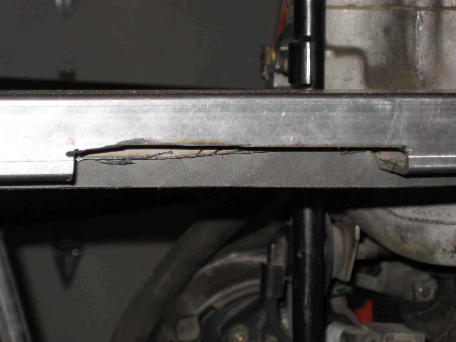
I also got around to adding some extra bracing to the engine bay. The top pic is a removable brace that goes over the transmission tunnel. This makes it much easier to get the engine in and out. The bottom pic is the brace on the drivers side of the engine bay. I also added one to the passenger side as well.
Thursday, June 28, 2012
D96-97: Front End Rebuild + Radiator Mounts
I've never been happy with the front uprights I had, so I decided to rebuild these. Below is the new set. Now, both uprights are 1 1/2" square 1/8" tube instead of the normal 1" 16awg. This should provide plenty of strength to the upper a-arm mounts. If (big if) I keep the upper mounts in single shear, these will provide a much stronger mounting point and should hold up better to the torsional load created.
I haven't added the 3/4" DOM tube yet, but the front and back will now be in-line. I haven't figured out how to modify the upper a-arm yet. With the two mounts being in-line, I need to figure out the best way of using the heim joints without maxing out their travel. With the old design they were already close to being maxed out. I might just have to settle for less points of adjustment.
I've also got the radiator mounted to the new uprights. I'm still using the factory BMW radiator and mount points. However, I'm mounting from the rear instead of the front of the radiator.
The last piece of progress was finally adding some supports to top level of the frame in the engine bay. This is also a better view of the radiator upper mounts.
I haven't added the 3/4" DOM tube yet, but the front and back will now be in-line. I haven't figured out how to modify the upper a-arm yet. With the two mounts being in-line, I need to figure out the best way of using the heim joints without maxing out their travel. With the old design they were already close to being maxed out. I might just have to settle for less points of adjustment.
I've also got the radiator mounted to the new uprights. I'm still using the factory BMW radiator and mount points. However, I'm mounting from the rear instead of the front of the radiator.
The last piece of progress was finally adding some supports to top level of the frame in the engine bay. This is also a better view of the radiator upper mounts.
Wednesday, June 20, 2012
D93-95: Floor + Welding + Update
I'm back! After 3 months of training, Ride the Rockies has come and gone. Turned into a shorter week than planned because of a knee injury, but still had 4 good days and 300 miles on the bike.
Here's a pic of my brother and I at the top of Independence Pass. This was after 6000 ft of climbing, most in the last 15 mi. I've been wanting to climb this pass for years and was excited to finally get the chance.
On to the build progress. I've spent a little time over the past few days getting the floor finished and working on finish welding the frame. I'd say I'm 95% complete on welding... but I keep finding more that needs to be finished.
I'm also working on the upper a-arm support to eliminate the "single shear" in the current design and figuring out where the shocks are going to mount.
Here's a pic of my brother and I at the top of Independence Pass. This was after 6000 ft of climbing, most in the last 15 mi. I've been wanting to climb this pass for years and was excited to finally get the chance.
On to the build progress. I've spent a little time over the past few days getting the floor finished and working on finish welding the frame. I'd say I'm 95% complete on welding... but I keep finding more that needs to be finished.
I'm also working on the upper a-arm support to eliminate the "single shear" in the current design and figuring out where the shocks are going to mount.
Wednesday, April 4, 2012
D88-90: Firewall v2 + Unpowered Brakes
I haven't had a chance to post from the last few days in the garage, so here's a quick update. I've wanted to redo the upper firewall for the driver side since the first one went in. Here is my second go around. I think it turned out much cleaner. I also moved the mount for the steering shaft up a little bit to simplify the final weld and move the steering u-joint away from the engine mount.
After removing the brake booster, the master cylinder sat a little close to the firewall. I build a "shim" to move it out by about 3/8".
Here is the new firewall with everything attached. I'm so much happier with the way this version turned out.
With the brake booster removed, I had to shorten the push rod from the pedal to the master cylinder. Here is the shortened version.
Below is the brake pedal with the new push rod installed. Now I just need to figure out how to make sure that the brake pedal doesn't swing back and the push rod come out. This was all held in place by brake booster before. Oh, and I hope that I don't need that booster. Ha.
After removing the brake booster, the master cylinder sat a little close to the firewall. I build a "shim" to move it out by about 3/8".
Here is the new firewall with everything attached. I'm so much happier with the way this version turned out.
With the brake booster removed, I had to shorten the push rod from the pedal to the master cylinder. Here is the shortened version.
Below is the brake pedal with the new push rod installed. Now I just need to figure out how to make sure that the brake pedal doesn't swing back and the push rod come out. This was all held in place by brake booster before. Oh, and I hope that I don't need that booster. Ha.
Sunday, March 11, 2012
D85-86: Frame Supports & Ride the Rockies
It's been a while since I've posted, mostly because it's been a while since I've worked on the car. Partly the weather and partly because I got into Ride the Rockies.
Ride the Rockies is a Colorado bike (bicycle) ride through the Rocky Mountains. The route changes every year, but this year it's 6 days, 442 miles, from Gunnison, CO to Ft. Collins, CO. What does this have to do with building a locost? Well, riding 442 miles takes some serious training which means I have and will be spending an increasingly greater amount of my free time on my bike instead of in the garage. I still plan on continuing the build, but it'll likely be at a slower pace than usual.
This weekend, I found myself motivated to get this frame finished. I've past my one year anniversary and I'm still working on the frame. I know everyone says it takes the majority of the build time, but I had NO idea it would take this long. With a few free hours I got almost all of the remainder frame supports cut and tacked into place. The two picks are the rear bulkhead behind the seats and the side of the frame (both sides are finished).
Ride the Rockies is a Colorado bike (bicycle) ride through the Rocky Mountains. The route changes every year, but this year it's 6 days, 442 miles, from Gunnison, CO to Ft. Collins, CO. What does this have to do with building a locost? Well, riding 442 miles takes some serious training which means I have and will be spending an increasingly greater amount of my free time on my bike instead of in the garage. I still plan on continuing the build, but it'll likely be at a slower pace than usual.
This weekend, I found myself motivated to get this frame finished. I've past my one year anniversary and I'm still working on the frame. I know everyone says it takes the majority of the build time, but I had NO idea it would take this long. With a few free hours I got almost all of the remainder frame supports cut and tacked into place. The two picks are the rear bulkhead behind the seats and the side of the frame (both sides are finished).
Thursday, December 29, 2011
D69: Upper A-Arm D1 + Engine Removal
With the lower arms together, it was time to get the upper arms built. These are much easier to assemble as they are adjustable and don't require everything to be precisely positioned.
The concept here is very similar to that of Jim McSorely over at sevenesque.com except a little more homemade. I got the weld bungs for a great discount making it cheaper to make my own tubes instead of getting real swaged tubes.
My wife and I were having people over for New Years Eve and the garage was needed for some of the festivities... so I began pulling everything apart. Learning from my last experience of installing the motor, I decided to remove the tube that goes across the top of the transmission right behind the engine block. This allowed me to lift the engine straight up and out. Much easier. I plan on making that tube removable to make this process easier in the future without having to cut that tube out every time.
The concept here is very similar to that of Jim McSorely over at sevenesque.com except a little more homemade. I got the weld bungs for a great discount making it cheaper to make my own tubes instead of getting real swaged tubes.
Front tube with fixed end.
|
Rear tube with clevis end.
|
Upper assembly attached to the spindle.
The tabs on the ball joint sleeve are cut from 3/8" plate.
My wife and I were having people over for New Years Eve and the garage was needed for some of the festivities... so I began pulling everything apart. Learning from my last experience of installing the motor, I decided to remove the tube that goes across the top of the transmission right behind the engine block. This allowed me to lift the engine straight up and out. Much easier. I plan on making that tube removable to make this process easier in the future without having to cut that tube out every time.
Monday, December 26, 2011
D66:Frame Rear End D2
I had some time today to work on the rear end of the frame again. I now have most of it done. It turned out to be a little more complicated than I had originally thought because the width of the frame is 48" which means that some of the rear tires will be within the frame. This is going to make mounting the body panels and fenders a little more challenging as well.
The first step today was mounting one of the rear wheels. I had to see how much the frame would overlap the tire and then make sure that the tire had a full range of motion without bumping into any of the frame. All the while, I was thinking about about extra supports to strengthen everything, how to mount the shock and spring and how to mount the fender as well.
Below is the clearance between the rear wheel and the back of the frame. It's just enough to give the wheel full range of motion without contact.
One of the changes I had to make was shrinking the 3" radius rear corner down to a 1" radius. This allows for a little more clearance for the rear wheel. I'm sure this will come back to bite me at me when I'm installing body panels... but, that'll be a problem for another day.
Finally, a picture of the entire rear end. The nice thing about this design is that it isn't load bearing. This allows me to skimp on extra supports.
The first step today was mounting one of the rear wheels. I had to see how much the frame would overlap the tire and then make sure that the tire had a full range of motion without bumping into any of the frame. All the while, I was thinking about about extra supports to strengthen everything, how to mount the shock and spring and how to mount the fender as well.
Below is the clearance between the rear wheel and the back of the frame. It's just enough to give the wheel full range of motion without contact.
One of the changes I had to make was shrinking the 3" radius rear corner down to a 1" radius. This allows for a little more clearance for the rear wheel. I'm sure this will come back to bite me at me when I'm installing body panels... but, that'll be a problem for another day.
Finally, a picture of the entire rear end. The nice thing about this design is that it isn't load bearing. This allows me to skimp on extra supports.
Sunday, December 18, 2011
D64:Frame Rear End
I had some time this afternoon out in the garage and the weather was beautiful. I decided to give the steering a break for a day and try to get the rear end finished. The CAD drawing is what I was going off to build the rear end of the frame. I've made some changes here from the book, as usual. Most of the changes are needed to incorporate the donor rear end without major mods.
I tried to mock up the wheels and fenders in the CAD to get an idea of what it'll look like assembled. We'll see how it looks when it actually comes together.
I've finished about half of the rear end so far. I still need to add a couple of pieces to the rear and then add the sides in as well. I'm hoping that all comes together pretty quickly.
One change from the book is using square tubing and a flat strip instead of a round tube on the top of the rear. I just didn't want to spend the extra cash buying round tube when I had plenty of square in the garage. I also didn't want to figure out bending the tube either for the corners. I think this solution might not be the prettiest in the end, but it'll work... and it's locost.
I tried to mock up the wheels and fenders in the CAD to get an idea of what it'll look like assembled. We'll see how it looks when it actually comes together.
I've finished about half of the rear end so far. I still need to add a couple of pieces to the rear and then add the sides in as well. I'm hoping that all comes together pretty quickly.
One change from the book is using square tubing and a flat strip instead of a round tube on the top of the rear. I just didn't want to spend the extra cash buying round tube when I had plenty of square in the garage. I also didn't want to figure out bending the tube either for the corners. I think this solution might not be the prettiest in the end, but it'll work... and it's locost.
Tuesday, November 22, 2011
D60:Pedal Mounting D5 + Steering Column Install D1
Below is the gas pedal mount from D4 tacked in with the gas pedal assembly installed. This also shows the outer bushing case that will hold the steering column.
With all three pedals in, the steering column mounting is underway along with figuring out steering linkage from the column to the rack. Here is a view of the pedal box with the steering column "installed".
I needed to cut one last hole through the firewall to pass the steering column through. As you can see below... I should have measured twice. Instead I cut the hole in the wrong spot and resorted to using a pair of tin snips to ugly up the hole, but remove enough material to give the column enough clearance. When I pull everything out to paint the frame, I'll work on making that hole a little cleaner.
One of the next items on the list is to figure out the extra linkage needed to connect the steering column to the rack. The issue I'm running into is that BMW doesn't exactly use commonly available steering parts. Some investigation is definitely needed to get this designed and built out.
Last item completed today was getting the clutch line installed. One big advantage to using the factory parts is I can take the original clutch line and with a little bending get it in and installed. This took all of 10 minutes tops. Now I wish I hadn't broken the bleeder fitting off in the clutch slave cylinder the last time I got the engine installed in the frame. Now I have to get a new slave cylinder before the clutch can be crossed off the to do list.
Monday, November 21, 2011
D59:Pedal Mounting D4
The first thing on the to do list today was finishing off the frame mods to add the lower support for the pedal firewall. Below is the rest of the frame added for the bottom. It's also at about 15 degrees. The rest of the framing to add material for welding hasn't been added yet, but I ended up adding that extra sheet all the way around the frame.
With the firewall frame finished and the firewall tacked in, next up was getting the top mount for the pedal assembly mount. Below, a new cross bar with a mount can be seen in the top right.
With the clutch and brake pedal in, I needed to figure out the steering column positioning. It took some time to decide if I wanted to use the factory method/mount to pass the steering column through the firewall. This involves using the original gas pedal assembly which combines a plastic bushing to pass hold the front end of the steering column.
Using the factory brake booster and pedal assembly limits the options for the steering column a little as it would be pretty hard to pass the steering column between the pedals in the center of the pedal box. This leaves mounting the steering column at an angle... which until I starting working on this part of the car I didn't realize that my M3 is setup the same way. How could I drive a car for 5 years and not realize the steering wheel wasn't first, centered on the drivers seat, and second, wasn't pointing straight out of the dash. I decided to use the original gas pedal assembly. Below is the the original firewall mounted on 1/2" square tubing as supports. I'll fill in the empty parts before finally welding the mount into the frame. ...and the mount above with the factory gas pedal.
Sunday, November 20, 2011
D58:Pedal Mounting D3
With the pedal firewall mount assembled, it wass time to get it mounted in the frame. The first issue that I came across was that I cut the sheet too small and there wasn't any overlap on the frame. I'm realizing that one of the issues with using flux core wire and no shielding gas is welding any thin gauge sheet is almost impossible without burning through every quarter inch. Frustrating! To remedy this, I framed out the frame where the firewall sheet will be mounted. The beginning of this frame is shown below.
Next problem was that I needed to mount the brake booster higher than I thought to clear the frame. The additional height that I added when building the 15 degree angle on top of the pedal box was about 1/4" too low, of course. Easy fix, just cut out a notch to fit the pedal assembly mount.
Below is the firewall sheet mocked up to show the final assembly and make sure everything fits before making the rest of the frame changes.
Finally, the whole pedal assembly installed to show the brake booster in place along with the pedal mount and clutch master cylinder. There will need to be some additional changes to the frame to fill in the space on the bottom half of the firewall sheet along with adding some more support to the firewall.
Monday, November 14, 2011
D56-57:Pedal Mounting D1/2
I spent the last couple of days working on the pedal assembly and getting the factory pedals mounted in the frame. The first change needed was angling the mount about 15 degrees to replicate the factory mounting of the brake booster and master cylinder. In the first two pics are the modifications made to the frame to achieve this angle.
The next step was integrating the original mounting plates into the new firewall. Below is the firewall from the BMW that will be used instead of recreating it in new sheet metal. The original plan was to make the new firewall a single piece. After mocking everything up, it was obvious that another solution would be needed.
The new solution is a 2 piece solution. The top half of the firewall to mount the pedal assembly and then add the bottom half as a separate piece.
Below is the top half with original firewall wall piece and the new firewall separate...
...and then on top of each other which will be the final assembly. Reusing the original means I don't need to go out an buy all the necessary hole saws to replicate the original. I'm trying to keep this as low cost as possible.
Subscribe to:
Posts (Atom)