Showing posts with label upper a-arm. Show all posts

Wednesday, July 11, 2012

D99: Scuttel & Upper A-Arm

I've been dying to get an idea of what this car will eventually look like, so I threw some spare wood together to build a scuttle mock up. I'm still deciding what I'm going to build the scuttle out of in the end, but for now, at least I can picture it.

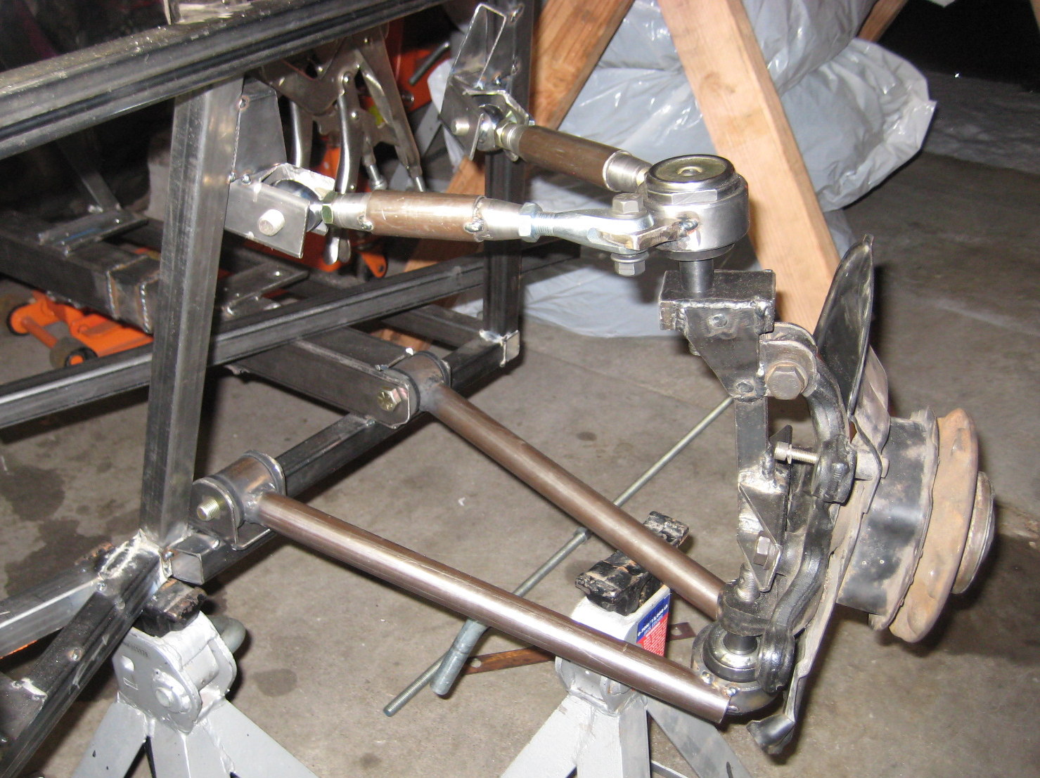
I also rebuilt the upper a-arms. I had to do this to mount them to the new geometry created by rebuilding the front end. Below is the new design built out. It's not as easy to adjust, but it gives more space for the shock and of course, works with the frame redesign.

Oh, and I built some shock mounts. I'm not finalized on the placement of the upper mount yet, but it'll do for now.

Thursday, June 28, 2012

D96-97: Front End Rebuild + Radiator Mounts

I've never been happy with the front uprights I had, so I decided to rebuild these. Below is the new set. Now, both uprights are 1 1/2" square 1/8" tube instead of the normal 1" 16awg. This should provide plenty of strength to the upper a-arm mounts. If (big if) I keep the upper mounts in single shear, these will provide a much stronger mounting point and should hold up better to the torsional load created.

I haven't added the 3/4" DOM tube yet, but the front and back will now be in-line. I haven't figured out how to modify the upper a-arm yet. With the two mounts being in-line, I need to figure out the best way of using the heim joints without maxing out their travel. With the old design they were already close to being maxed out. I might just have to settle for less points of adjustment.

I've also got the radiator mounted to the new uprights. I'm still using the factory BMW radiator and mount points. However, I'm mounting from the rear instead of the front of the radiator.

The last piece of progress was finally adding some supports to top level of the frame in the engine bay. This is also a better view of the radiator upper mounts.

Thursday, February 23, 2012

D83-84: Upper A-Arm Mounts

I got a little time tonight and a last weekend in the garage working on the upper a-arm mounts and here is (hopefully) the final product.

I replaced the rear vertical tube with 1 1/2" square tube. This should allow for a stronger support of the upper mount. I'm mounting the upper a-arm to a piece of 3/4" DOM (.120 wall) tubing. This mount allows me to use a 1/2" bolt.
The front mount is 3/4" DOM through a piece of 1"x2" tubing. I tried to align the mount so that the tubing was horizontal, but more importantly that the mount is 9" above the lower control arm. I'm still trying to figure out how to add sufficient support to this mount.
Here is the finished product with the upper a-arm "installed". One thing I like about this design is there is plenty of space to fit a coilover shock and spring.
The last part of the front suspension is modifying the driver side steering rod end. Then it is on to final welding the frame and building the cage.

Tuesday, January 31, 2012

D82: Front Suspension Rebuild #4 D2

I built new mounts for the upper a-arms. I've got the mounting bolts vertical now instead of horizontal. I wanted to try this out and see if it would work better than the old design.
With the new suspension design, I needed to move the steering arm from mounting on the bottom of the spindle to the top of the mount. This required a new steering arm. I've used 1/2" rod ends on the spindle side. On the steering rack side, I cut the threaded portion of the factory arm off and used it as an "M14x1.5" weld bung. Saved me having to buy a random metric tap.
A picture of the completed lower control arm and the upper a-arm along with the new steering arm all assembled with the tire.

Saturday, January 7, 2012

D72: Upper A-Arm Mounts

If you noticed, I missed day 71. I finished the second lower a-arm a couple of days ago and didn't blog about it since it looks almost identical to the first one in D70.

With one upper a-arm finished, I was ready to get the mounts in to make sure everything would come together. I also needed to figure out how long each tube + weld bungs is going to be.

Last night I spent a little time with CAD figuring out the layout of the mounts. I went in knowing the following:
  • The mounts would attach to the two uprights
  • The mounts would be made out of 1/8" thick 1 1/2" square tubing
  • The angles of each of these mounts is 17 deg and 30 deg
I didn't want the rod ends to operate at an extreme angle, so I figured out a rough estimate for the angle of the front and rear.

CAD design of mount layouts. (They are wider than 9in.)

Next up was some CAD to figure out how far apart the lower and upper mount should be. I can't remember where I read this, but I remember 1" of travel should change the camber by 1 degree. The design has the distance between the lower ball joint pivot point and the ground along with the intended ride height of 6" (close to the donor) and then measurements from the frame.

CAD design of front suspension.

Upper a-arm mounts.

This design creates an optical illusion. Every time I look at it, I can't believe that the mounts are parallel. I keep seeing funky angles or thinking one mount is crooked.
[Top] Finished mounts + upper a-arm installed.

[Side] Finished upper/lower arms + mounts.
Note: The new location of the rear lower a-arm mount required a small addition to the frame. The mount only covered about a 1/4" in of the frame tube. It needed a little more reinforcement. I'm planning on more support later.

Thursday, December 29, 2011

D69: Upper A-Arm D1 + Engine Removal

With the lower arms together, it was time to get the upper arms built. These are much easier to assemble as they are adjustable and don't require everything to be precisely positioned.

The concept here is very similar to that of Jim McSorely over at sevenesque.com except a little more homemade. I got the weld bungs for a great discount making it cheaper to make my own tubes instead of getting real swaged tubes.

Front tube with fixed end.
Rear tube with clevis end.

Upper assembly attached to the spindle.
The tabs on the ball joint sleeve are cut from 3/8" plate.

My wife and I were having people over for New Years Eve and the garage was needed for some of the festivities... so I began pulling everything apart. Learning from my last experience of installing the motor, I decided to remove the tube that goes across the top of the transmission right behind the engine block. This allowed me to lift the engine straight up and out. Much easier. I plan on making that tube removable to make this process easier in the future without having to cut that tube out every time.

Print