With one upper a-arm finished, I was ready to get the mounts in to make sure everything would come together. I also needed to figure out how long each tube + weld bungs is going to be.
Last night I spent a little time with CAD figuring out the layout of the mounts. I went in knowing the following:
- The mounts would attach to the two uprights
- The mounts would be made out of 1/8" thick 1 1/2" square tubing
- The angles of each of these mounts is 17 deg and 30 deg
CAD design of mount layouts. (They are wider than 9in.)

Next up was some CAD to figure out how far apart the lower and upper mount should be. I can't remember where I read this, but I remember 1" of travel should change the camber by 1 degree. The design has the distance between the lower ball joint pivot point and the ground along with the intended ride height of 6" (close to the donor) and then measurements from the frame.
CAD design of front suspension.

Upper a-arm mounts.

This design creates an optical illusion. Every time I look at it, I can't believe that the mounts are parallel. I keep seeing funky angles or thinking one mount is crooked.
[Top] Finished mounts + upper a-arm installed.

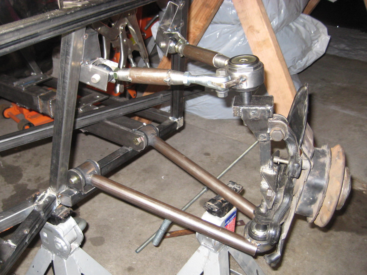
[Side] Finished upper/lower arms + mounts.
No comments:
Post a Comment