
Friday, December 30, 2011
Lower A-Arm: The Realization
While pulling everything apart, I put the front end back together to take a moment and appreciate all the work I'd accomplished the days before. I even attached the steering linkage and turned the wheel around a couple of... oh crap! I only get one full turn out of the wheel before the rim makes contact with the lower a-arm.
 Since I'm not a huge fan of 17 point turns to flip a U, it looks like it's back to the drawing board for round three of lower a-arm design and rebuild.

Thursday, December 29, 2011
D69: Upper A-Arm D1 + Engine Removal
With the lower arms together, it was time to get the upper arms built. These are much easier to assemble as they are adjustable and don't require everything to be precisely positioned.
The concept here is very similar to that of Jim McSorely over at sevenesque.com except a little more homemade. I got the weld bungs for a great discount making it cheaper to make my own tubes instead of getting real swaged tubes.
My wife and I were having people over for New Years Eve and the garage was needed for some of the festivities... so I began pulling everything apart. Learning from my last experience of installing the motor, I decided to remove the tube that goes across the top of the transmission right behind the engine block. This allowed me to lift the engine straight up and out. Much easier. I plan on making that tube removable to make this process easier in the future without having to cut that tube out every time.

The concept here is very similar to that of Jim McSorely over at sevenesque.com except a little more homemade. I got the weld bungs for a great discount making it cheaper to make my own tubes instead of getting real swaged tubes.
Front tube with fixed end.
 |
Rear tube with clevis end.
 |
Upper assembly attached to the spindle.
The tabs on the ball joint sleeve are cut from 3/8" plate.
The tabs on the ball joint sleeve are cut from 3/8" plate.
 |
 |
My wife and I were having people over for New Years Eve and the garage was needed for some of the festivities... so I began pulling everything apart. Learning from my last experience of installing the motor, I decided to remove the tube that goes across the top of the transmission right behind the engine block. This allowed me to lift the engine straight up and out. Much easier. I plan on making that tube removable to make this process easier in the future without having to cut that tube out every time.

Wednesday, December 28, 2011
D68: Lower A-Arm D2
The second day working on the lower a-arm started out with a new design. Attach the tubes directly to the ball joint sleeve. This required some grinding to get all the necessary notches into the tubes. I needed something to easily hold a tube while I could grind it down.


 I am much happier with the second iteration of the a-arm design.
A quick note here. Use a threaded rode when mocking up the bushing sleeves before tacking them in place. This will ensure they are straight and won't bind with travel. I thought I had a decent jig setup until I installed the arm on the frame with the rear mount loose and realized the mount moved when rotating the arm. Turns out the bushing sleeves weren't in line.
The tube holder device thingy.

The front tube and ball joint sleeve mocked up.

The finished product installed.

Both sides finished. One with a ball joint installed.

Lower a-arm with spindle installed.

A quick note here. Use a threaded rode when mocking up the bushing sleeves before tacking them in place. This will ensure they are straight and won't bind with travel. I thought I had a decent jig setup until I installed the arm on the frame with the rear mount loose and realized the mount moved when rotating the arm. Turns out the bushing sleeves weren't in line.
Tuesday, December 27, 2011
D67: Lower A-Arm D1
Here is my first attempt at the lower a-arms. The plan was to make a right triangle shape to simulate the factory control arms. A single plate welded to the ball join sleeve would link the sleeve to the tubes running back to the frame.


When I finally got all the pieces mocked up I decided I didn't like the idea of cutting a notch in the tube to attach it to the plate. I feel like this is asking for failure at the end of the notch. Final result of day 1: mulligan.
3/8" plate with a template outline.

The finished plate next to the sleeve.

The bushing sleeves, front tube, plate and sleeve mocked up.

When I finally got all the pieces mocked up I decided I didn't like the idea of cutting a notch in the tube to attach it to the plate. I feel like this is asking for failure at the end of the notch. Final result of day 1: mulligan.
Monday, December 26, 2011
D66:Frame Rear End D2
I had some time today to work on the rear end of the frame again. I now have most of it done. It turned out to be a little more complicated than I had originally thought because the width of the frame is 48" which means that some of the rear tires will be within the frame. This is going to make mounting the body panels and fenders a little more challenging as well.
The first step today was mounting one of the rear wheels. I had to see how much the frame would overlap the tire and then make sure that the tire had a full range of motion without bumping into any of the frame. All the while, I was thinking about about extra supports to strengthen everything, how to mount the shock and spring and how to mount the fender as well.
Below is the clearance between the rear wheel and the back of the frame. It's just enough to give the wheel full range of motion without contact.
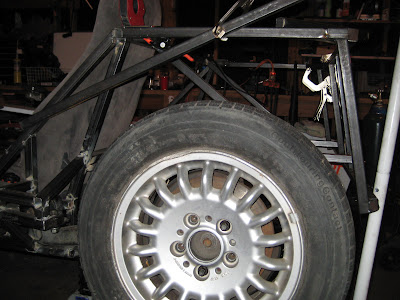 One of the changes I had to make was shrinking the 3" radius rear corner down to a 1" radius. This allows for a little more clearance for the rear wheel. I'm sure this will come back to bite me at me when I'm installing body panels... but, that'll be a problem for another day.
 Finally, a picture of the entire rear end. The nice thing about this design is that it isn't load bearing. This allows me to skimp on extra supports.

The first step today was mounting one of the rear wheels. I had to see how much the frame would overlap the tire and then make sure that the tire had a full range of motion without bumping into any of the frame. All the while, I was thinking about about extra supports to strengthen everything, how to mount the shock and spring and how to mount the fender as well.
Below is the clearance between the rear wheel and the back of the frame. It's just enough to give the wheel full range of motion without contact.


Thursday, December 22, 2011
New Blog Page:Parts
... and one more new blog page. I plan on keeping a list of all parts that are either sourced from a junk yard or purchased to complete this build.
New Blog Page:Tools
I've added a new page to my blog that has a list of all the tools used for this project. So far I only have the big items, but I'm planning on making this as comprehensive as possible.
Subscribe to:
Posts (Atom)